📡 4G/5G Networks
Deep dive into modern cellular network technologies: 4G LTE and 5G architecture, protocols, authentication, and practical applications.
Table of Contents
- Big Picture: What Mobile Networks Do
- 4G LTE Architecture
- How 4G Works (Practical Example)
- 4G Voice (VoLTE)
- Real-Time Traffic in 4G
- 5G Architecture
- How 5G Works (Practical Example)
- AS vs NAS (Critical Concept)
- Control Plane vs User Plane
- 5G Interfaces (N2, N3, N4, N6)
- 5G-AKA Authentication
- 5G Voice (VoNR)
- NGFW/SASE Alignment
- Key Takeaways
Big Picture: What Mobile Networks Do {#big-picture}
A cellular network provides the UE (phone/device) the following critical services:
- Connectivity: Get internet access to external networks
- Identity & Authentication: Verify subscriber is legitimate before granting service
- Mobility: Move between cells/towers without session drop or authentication restart
- Services: Support voice calls, SMS, real-time apps with QoS guarantees
Types of Traffic
- Normal Internet: Browsing, YouTube, downloads (best-effort)
- Real-Time: WhatsApp calls, Zoom, gaming (low latency, priority)
- Carrier Services: VoLTE/VoNR, SMS (highest priority)
4G LTE Architecture {#4g-lte-architecture}
High-Level Overview
UE (Device) ↔ eNodeB ↔ EPC (Core) ↔ Internet/IMS4G LTE Basics
- LTE: Long Term Evolution
- Standard: 3GPP Release 8 and beyond
- Spectrum: Multiple bands (2G, 3G, 4G frequencies)
- Peak Data Rate: Up to 300 Mbps (LTE-A)
- Latency: ~100ms round-trip
- Architecture: All-IP (no circuit switching)
Key Features
- Orthogonal Frequency Division Multiplexing (OFDM)
- MIMO (Multiple-Input Multiple-Output) support
- Improved spectral efficiency
- Flat network architecture (simplified core network)
EPC Components
1. UE (User Equipment)
- Phone + SIM (USIM)
- Stores secret key K for authentication
2. E-UTRAN (Radio Network)
eNodeB (eNB) - 4G Base Station/Tower
Responsibilities:
- Radio scheduling and resource allocation
- Handovers between cells
- Radio encryption (PDCP layer)
- PHY modulation and transmission
3. MME (Mobility Management Entity) — Control Plane
Functions:
- Attachment/detachment procedures
- Authentication orchestration (interacts with HSS)
- Mobility management (tracking area updates, handovers)
- Bearer setup signaling (initiates SGW/PGW allocation)
- Paging for incoming calls
Interfaces: S1-MME (to eNB), S6a (to HSS), S10 (to other MMEs)
4. SGW (Serving Gateway) — User Plane Anchor
Functions:
- Forwards user traffic between eNB and PGW
- Mobility anchor: maintains tunnels during eNB handovers
- Buffering of downlink packets when UE is temporarily unreachable
Interfaces: S1-U (to eNB), S5 (to PGW)
5. PGW (Packet Gateway) — Internet Exit
Functions:
- Allocates IP address to UE
- Charging/billing hooks
- NAT (if needed)
- Policy enforcement
- Connects to external Data Networks (DN): Internet, IMS
Interfaces: S5 (to SGW), S2a/S2b (to external networks/PDN)
6. HSS (Home Subscriber Server) — Subscriber Database
Stores:
- IMSI (International Mobile Subscriber Identity)
- Secret key K (for authentication)
- Subscription info (what services user is allowed to use)
- QoS profiles
Interfaces: S6a (to MME), Cx (to IMS)
7. PCRF (Policy and Charging Rules Function)
Functions:
- Policy control (which traffic is allowed)
- QoS rules (traffic prioritization)
- Charging/billing policies
Interfaces: Rx (to IMS/App servers), Gx (to PGW)
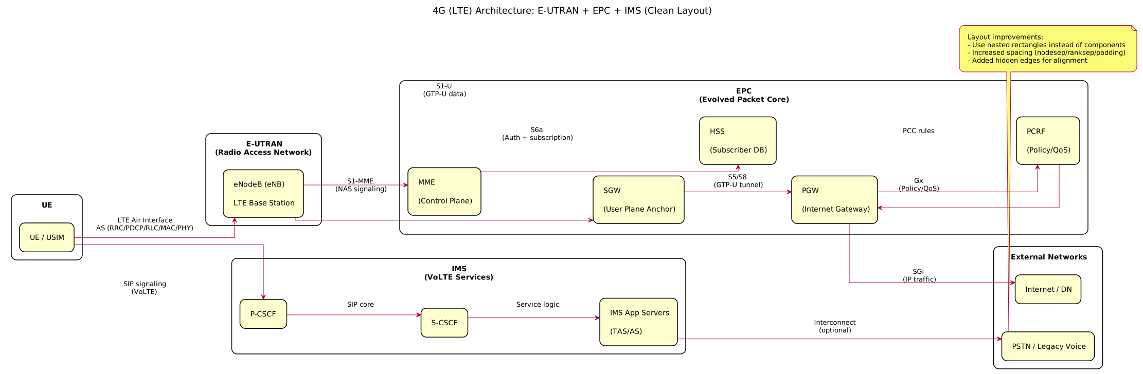
4G Architecture Diagram
 {:class=“diagram-img”}
Complete 4G architecture showing E-UTRAN, EPC components, IMS, and external networks with all interfaces (S1-MME, S1-U, S5/S8, S6a, Gx, SGi).
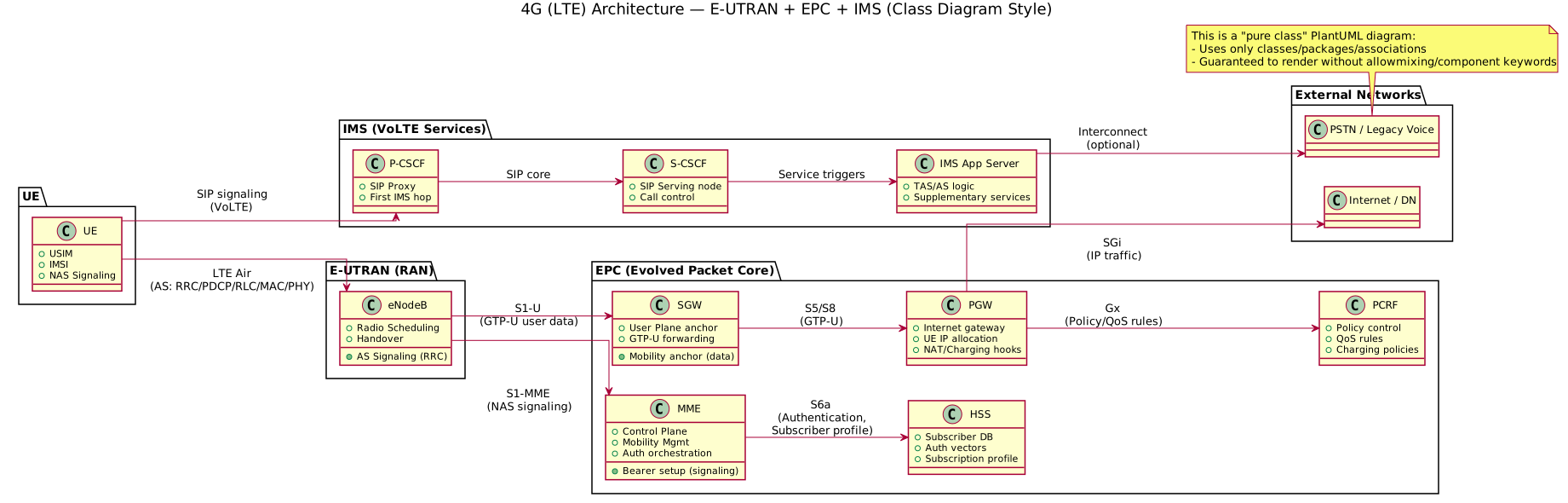
4G Architecture Class Diagram
 {:class=“diagram-img”}
Complete 4G architecture class-diagram showing E-UTRAN, EPC components, IMS, and external networks with all interfaces (S1-MME, S1-U, S5/S8, S6a, Gx, SGi).
How 4G Works (Practical Example) {#how-4g-works}
Scenario: Opening YouTube on LTE
Step 1: Attachment
- UE powers on, scans for eNB
- Sends Attach Request to MME via eNB
- MME authenticates UE using HSS/AuC (Authentication Center)
- Generates RAND, authentication vector
- UE computes response using secret K
- HSS validates response
Step 2: Bearer Setup
- MME requests SGW/PGW allocation for internet
- SGW/PGW provisions EPS Bearer
- UE receives IP address (via PGW)
Step 3: Data Flow User plane path:
UE ↔ eNB ↔ SGW ↔ PGW ↔ InternetData is tunneled using GTP-U (GPRS Tunneling Protocol - User Plane):
- Packets are wrapped in GTP tunnel between eNB-SGW and SGW-PGW
- Provides mobility: if UE moves to different eNB, SGW stays same (anchor)
Step 4: QoS Enforcement
- Bearer has QCI (QoS Class Identifier)
- YouTube traffic gets standard QCI, not prioritized
- Buffering happens in eNB (radio) and PGW (internet)
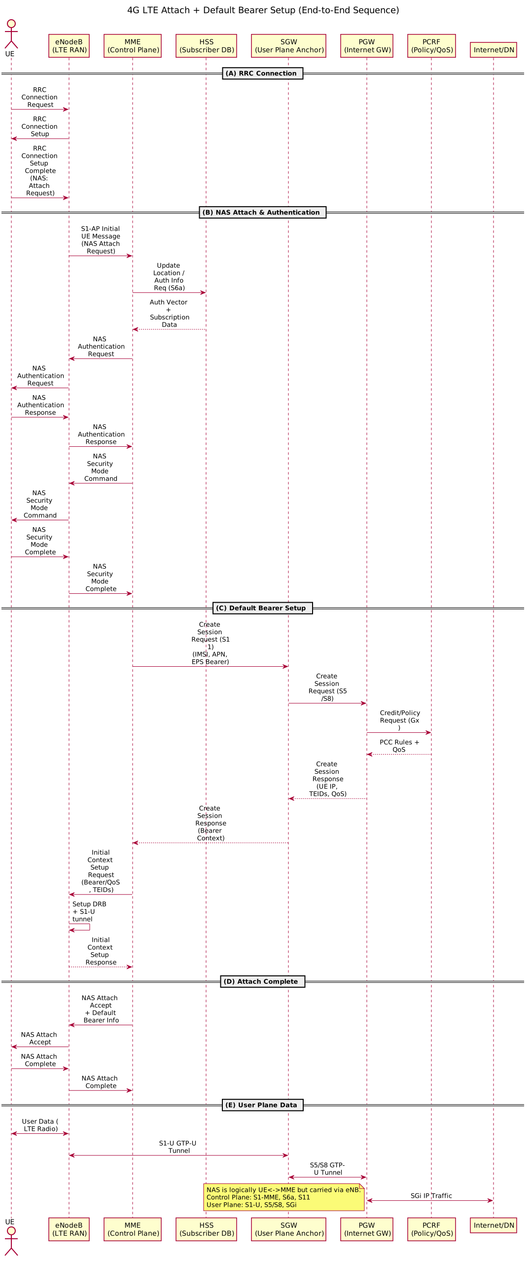
Attach & Bearer Setup Flow
 {:class=“diagram-img”}
Sequence diagram showing complete 4G attach procedure: RRC connection, NAS authentication with HSS, bearer setup via MME/SGW/PGW, and QoS policy from PCRF.
4G Voice (VoLTE) {#4g-voice-volte}
What is VoLTE?
VoLTE = Voice over LTE
LTE is packet-based, so voice is also carried as IP packets (not circuit-switched):
- Voice = RTP (Real-time Transport Protocol) over IP
- Signaling = SIP (Session Initiation Protocol)
VoLTE Architecture
VoLTE leverages the IMS (IP Multimedia Subsystem) core:
IMS Elements:
- P-CSCF: Proxy Call Session Control Function (gateway)
- S-CSCF: Serving CSCF (session server)
- I-CSCF: Interrogating CSCF (router)
- AS (Application Server): For services like call forwarding, voicemail
VoLTE Call Flow (High-Level)
-
UE registers with IMS using SIP
- Sends REGISTER message via P-CSCF
- S-CSCF authenticates and stores registration
-
Outgoing call:
- UE sends INVITE (SIP) via P-CSCF
- S-CSCF routes to callee
- Media path (voice RTP) established
-
LTE QoS Bearer:
- SMF/PCRF allocates high-priority bearer (e.g., QCI=1)
- Voice traffic gets low-latency, low-jitter handling
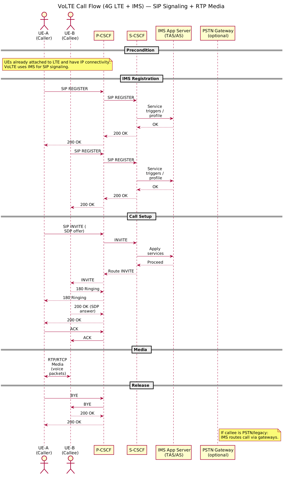
VoLTE Call Flow Diagram
 {:class=“diagram-img”}
Complete VoLTE call flow showing IMS registration, SIP INVITE/200 OK signaling via P-CSCF/S-CSCF, and RTP media establishment with QoS bearer (QCI=1).
Real-Time Traffic in 4G {#real-time-4g}
Real-time applications need:
- Low latency (~50ms one-way)
- Low jitter (stable delay)
- Stable uplink (no random drops)
EPS Bearers (QoS mechanism)
LTE uses EPS Bearers with QCI (QoS Class Identifier):
| QCI | Traffic Type | Latency | Loss Rate | Example |
|---|---|---|---|---|
| 1 | Conversational | <50ms | 10^-2 | VoLTE |
| 2 | Streaming | <150ms | 10^-3 | Video call |
| 3 | Interactive | <150ms | 10^-3 | Gaming |
| 4 | Background | <300ms | 10^-6 | Downloads |
Voice bearer (QCI=1) has highest priority in:
- eNB scheduling
- SGW buffering
- PGW QoS enforcement
5G Architecture {#5g-architecture}
High-Level Overview
UE (Device) ↔ gNB ↔ 5GC (Core) ↔ Internet/IMS5G NR Basics
- 5G NR: New Radio
- Standard: 3GPP Release 15 onwards
- Spectrum: Sub-6 GHz and mmWave (28, 39 GHz)
- Peak Data Rate: Up to 10 Gbps
- Latency: ~1ms round-trip (ultra-reliable low latency)
- Key Use Cases:
- eMBB: Enhanced Mobile Broadband (high speed)
- URLLC: Ultra-Reliable Low Latency Communications (factory automation)
- mMTC: Massive Machine-Type Communications (IoT)
Improvements over 4G
- 10x higher bandwidth and data rates
- 100x lower latency
- Greater capacity (massive MIMO: 64+ antennas)
- Energy efficiency (C-RAN, edge computing)
- Network slicing (virtual networks over same infrastructure)
Key Change: Service-Based Architecture (SBA)
4G: Fixed network topology with dedicated interfaces (S1, S11, S5, etc.)
5G: Microservices-based architecture
- NFs communicate via HTTP/2 REST APIs
- JSON-like message structures
- TLS/mTLS for security
- NRF (NF Repository Function) for service discovery
- Can scale functions independently
NG-RAN (Radio Side)
gNB = 5G base station (next-generation Node B)
- Supports both Sub-6 and mmWave
- Simplified interface to 5GC (N2, N3)
5G Core NFs (Network Functions)
1. AMF (Access & Mobility Management Function) — Control Plane
Replaces: MME (from 4G)
Functions:
- Registration (UE attachment)
- Mobility management (TAU equivalent: registration update)
- NAS message termination and ciphering
- Authentication orchestration (5G-AKA)
- Paging
Interfaces:
- N1 (UE ↔ AMF via gNB, NAS signaling)
- N2 (gNB ↔ AMF, NGAP)
- N11 (to SMF)
- N12 (to AUSF)
2. SMF (Session Management Function) — Control Plane
Replaces: Parts of MME + PGW (from 4G)
Functions:
- PDU session setup/modification (like EPS bearer)
- UPF selection and pooling
- QoS rules enforcement
- DNN (Data Network Name) routing
- Charging interaction
Interfaces:
- N11 (to AMF)
- N7 (to PCF)
- N4 (to UPF, configure forwarding rules)
3. UPF (User Plane Function) — User Plane Anchor
Replaces: SGW + PGW (from 4G, now unified)
Functions:
- Packet forwarding (routing)
- QoS enforcement (prioritization)
- Gateway to Internet/Data Networks
- Often deployed near edge for low latency
- Session buffering (for temporarily unreachable UE)
Interfaces:
- N3 (gNB ↔ UPF, GTP-U)
- N4 (SMF ↔ UPF, PFCP)
- N6 (UPF ↔ Internet/DN)
4. UDM (Unified Data Management) — Subscriber DB
Replaces: HSS (from 4G)
Functions:
- Stores SUPI (Subscription Permanent Identifier), secret key K
- Subscription profiles
- Authentication support (with ARPF)
Interfaces: N13 (to AMF), N10 (to SMF)
5. AUSF (Authentication Server Function) — Auth Validation
New in 5G
Functions:
- Validates UE response during 5G-AKA
- Derives session key material (K_SEAF)
Interfaces: N12 (to AMF), N13 (to UDM)
6. PCF (Policy Control Function) — Policy
Replaces: PCRF (from 4G)
Functions:
- Policy control (which traffic is allowed)
- QoS rules
- Charging policies
- Roaming policies
Interfaces: N7 (to SMF), Rx (to IMS)
7. NRF (NF Repository Function) — Service Registry
New in 5G
Functions:
- Service discovery (like Kubernetes service discovery)
- NF heart-beat monitoring
- Load balancing among NF instances
Interfaces: N27 (to all NFs)
8. NSSF (Network Slice Selection Function)
New in 5G
Functions:
- Selects network slice instance for UE
- Slice-specific AMF/SMF selection
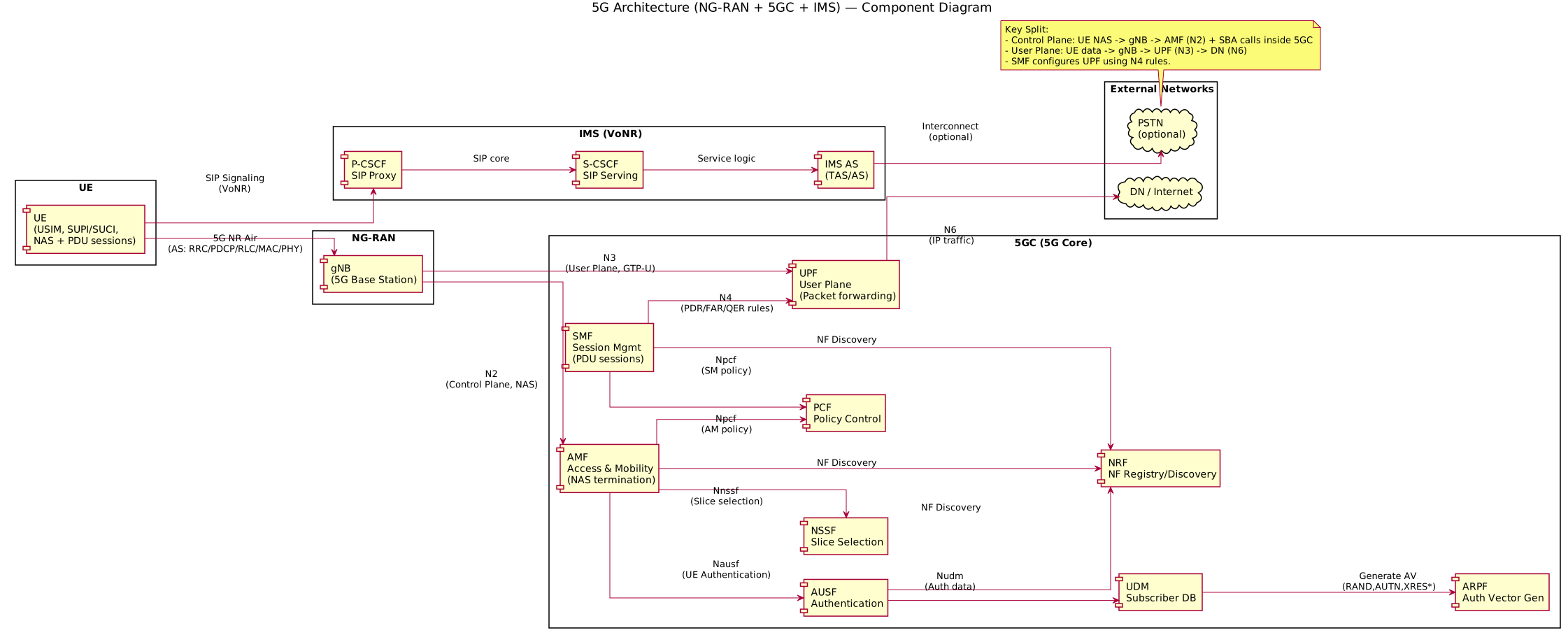
5G Architecture Diagram
 {:class=“diagram-img”}
5G architecture with NG-RAN (gNB), 5GC network functions (AMF, SMF, UPF, AUSF, UDM, PCF, NRF, NSSF), IMS, and external networks showing service-based architecture (SBA) with N1-N6 interfaces.
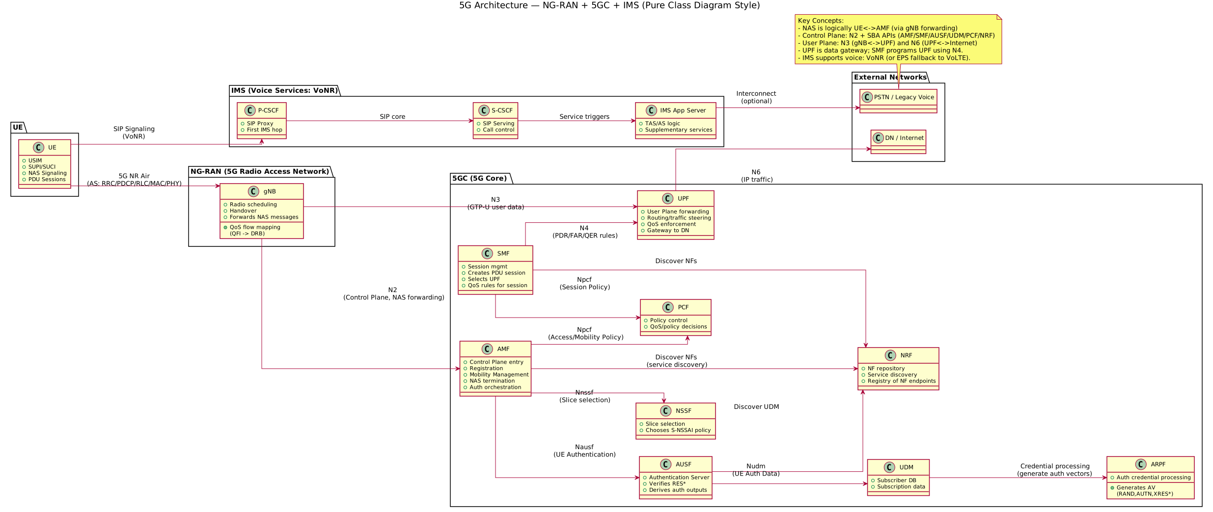
5G Architecture Class Diagram
 {:class=“diagram-img”}
5G architecture Class Diagram with NG-RAN (gNB), 5GC network functions (AMF, SMF, UPF, AUSF, UDM, PCF, NRF, NSSF), IMS, and external networks showing service-based architecture (SBA) with N1-N6 interfaces.
How 5G Works (Practical Example) {#how-5g-works}
Scenario: Opening YouTube on 5G
In 5G, an internet session = PDU Session (Protocol Data Unit Session)
Step 1: Registration
- UE powers on, connects to gNB
- UE sends Registration Request (NAS message)
- AMF receives, orchestrates 5G-AKA authentication with AUSF/UDM
- On success: K_SEAF (session encryption key) derived
Step 2: PDU Session Setup
- UE requests PDU session for DNN (Data Network Name, e.g., “internet”)
- AMF routes to SMF
- SMF selects UPF instance (may be edge UPF for low latency)
- SMF configures UPF forwarding rules via N4 (PFCP)
- UE receives IP address (via UPF/SMF)
Step 3: Data Flow
User plane path (much simpler than 4G):
UE ↔ gNB ↔ UPF ↔ InternetTunneling:
- GTP-U (still used, but no intermediate gateway like SGW)
- UPF can be deployed close to internet exit for lower latency
Step 4: QoS Enforcement
- SMF sends QoS rules to UPF via N4
- UPF enforces traffic shaping, prioritization
- YouTube traffic may get standard 5QI (5G QoS Indicator)
Step 5: Mobility
- UE moves to different gNB
- gNB change triggered at RRC (radio) level
- UPF stays same (anchor) — no SGW needed
- Simpler, faster handover
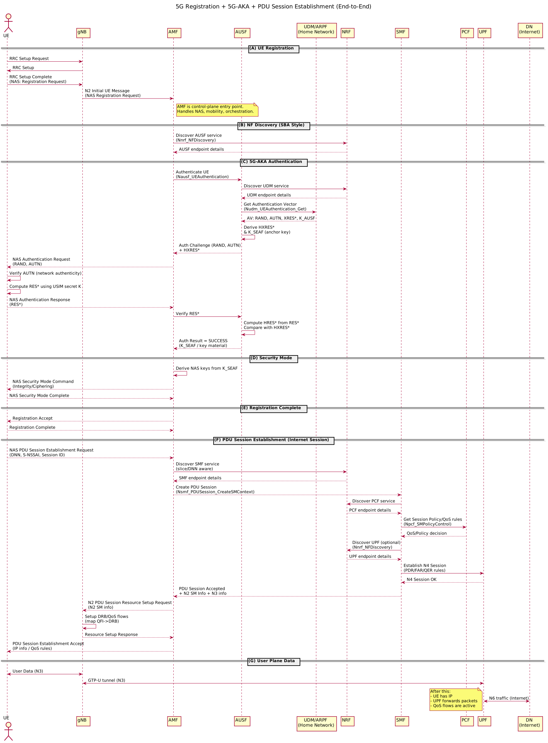
Complete 5G Flow Diagram
 {:class=“diagram-img”}
End-to-end sequence diagram showing: UE registration via gNB → AMF, NF discovery through NRF, 5G-AKA authentication with AUSF/UDM, PDU session establishment via SMF, and UPF configuration for data flow.
AS vs NAS (Critical Concept) {#as-vs-nas}
Telecom networks split control signaling into two logical layers:
Access Stratum (AS)
Definition: Radio access layer protocols
Scope: UE ↔ Base Station (eNB/gNB) over radio
Protocols:
- RRC: Radio Resource Control (connection setup, measurements)
- PDCP: Packet Data Convergence Protocol (compression, encryption)
- RLC: Radio Link Control (retransmission, segmentation)
- MAC: Medium Access Control (scheduling, multiplexing)
- PHY: Physical layer (modulation, coding, transmission)
Example Message: RRC measurement report, RRC reconfiguration
Layman’s Analogy: “How your phone talks to the tower over the radio waves”
Non-Access Stratum (NAS)
Definition: Core network control signaling
Scope: UE ↔ Core Network (MME/AMF) logically
- Physically: UE → Base Station → AMF (tunneled through AS)
Protocols:
- NAS 5GS (5G) or NAS EPS (4G)
Functions:
- Registration (attach/detach)
- Authentication (5G-AKA, KASME key derivation)
- Security mode setup (cipher/integrity algorithms)
- Mobility management (TAU, registration area update)
- PDU session requests (bearer setup)
- SMS, supplementary services
Example Message: Registration Request, PDU Session Establishment Request
Layman’s Analogy: “How your phone talks to the operator’s brain (core network)”
Key Difference: Security
- AS: Secured at radio layer (encrypt after RLC)
- NAS: Secured end-to-end UE ↔ AMF (encrypt after NAS layer)
If radio encryption broken, NAS is still protected!
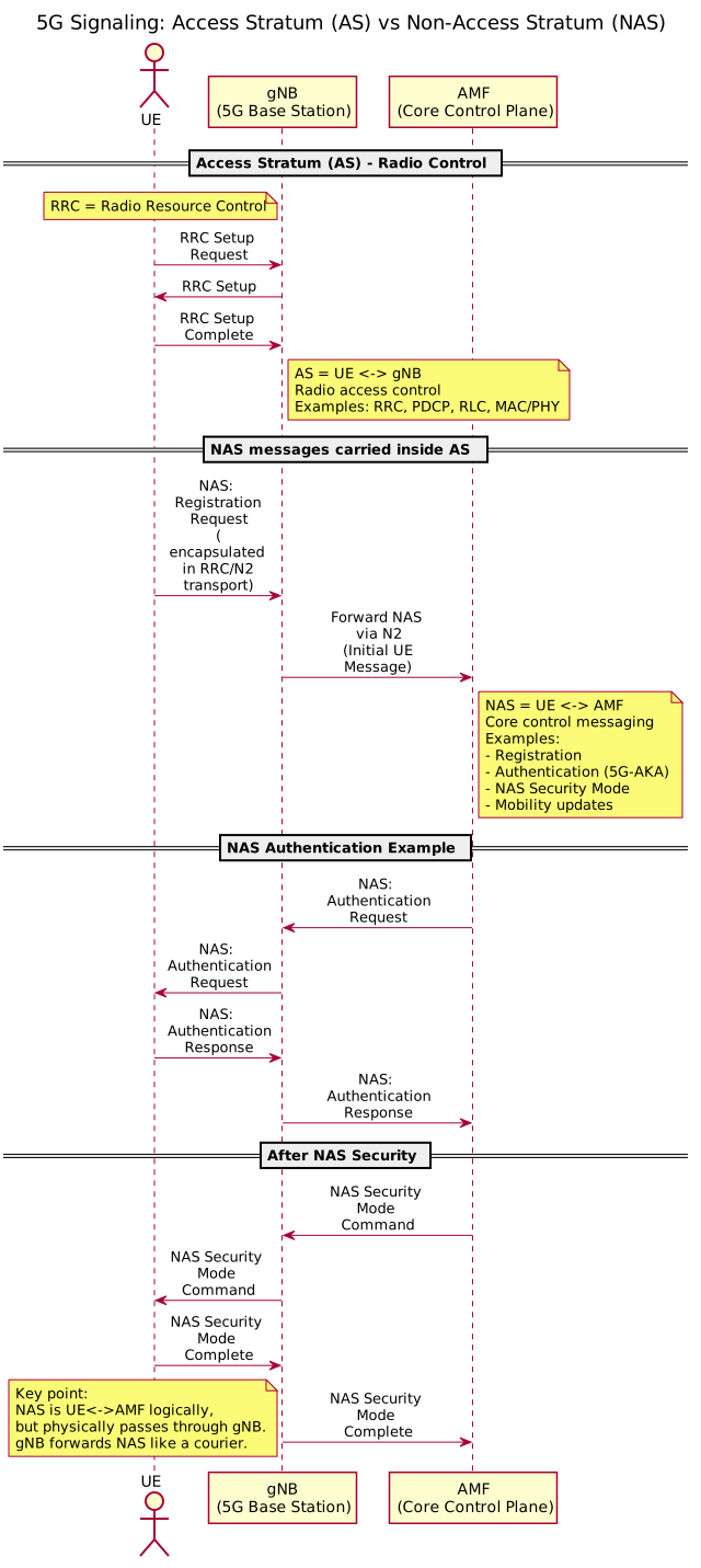
AS vs NAS Signaling Flow
 {:class=“diagram-img”}
Sequence diagram showing the separation between Access Stratum (AS) signaling (UE ↔ gNB: RRC, PDCP, RLC, MAC) and Non-Access Stratum (NAS) signaling (UE ↔ AMF: Registration, Authentication, Session) with NAS messages encapsulated through AS.
Control Plane vs User Plane {#control-plane-vs-user-plane}
Control Plane (CP)
Purpose: Setup, manage, tear down sessions
Functions:
- Registration
- Authentication
- Policy setup
- Session establishment
- Mobility management
In 4G (CP path):
UE ↔ eNB ↔ MME ↔ HSS/PCRFIn 5G (CP path, SBA):
UE ↔ gNB ↔ AMF ↔ AUSF/UDM/SMF/PCF (all via service APIs)Typical message: “Set up a bearer with 50 Mbps guarantee”
User Plane (UP)
Purpose: Carry actual user traffic (data, voice, video)
Flow: Real YouTube video stream, WhatsApp call audio
In 4G (UP path):
UE ↔ eNB ↔ SGW ↔ PGW ↔ InternetIn 5G (UP path):
UE ↔ gNB ↔ UPF ↔ InternetTypical message: “IP packet: 1.2.3.4 → YouTube server”
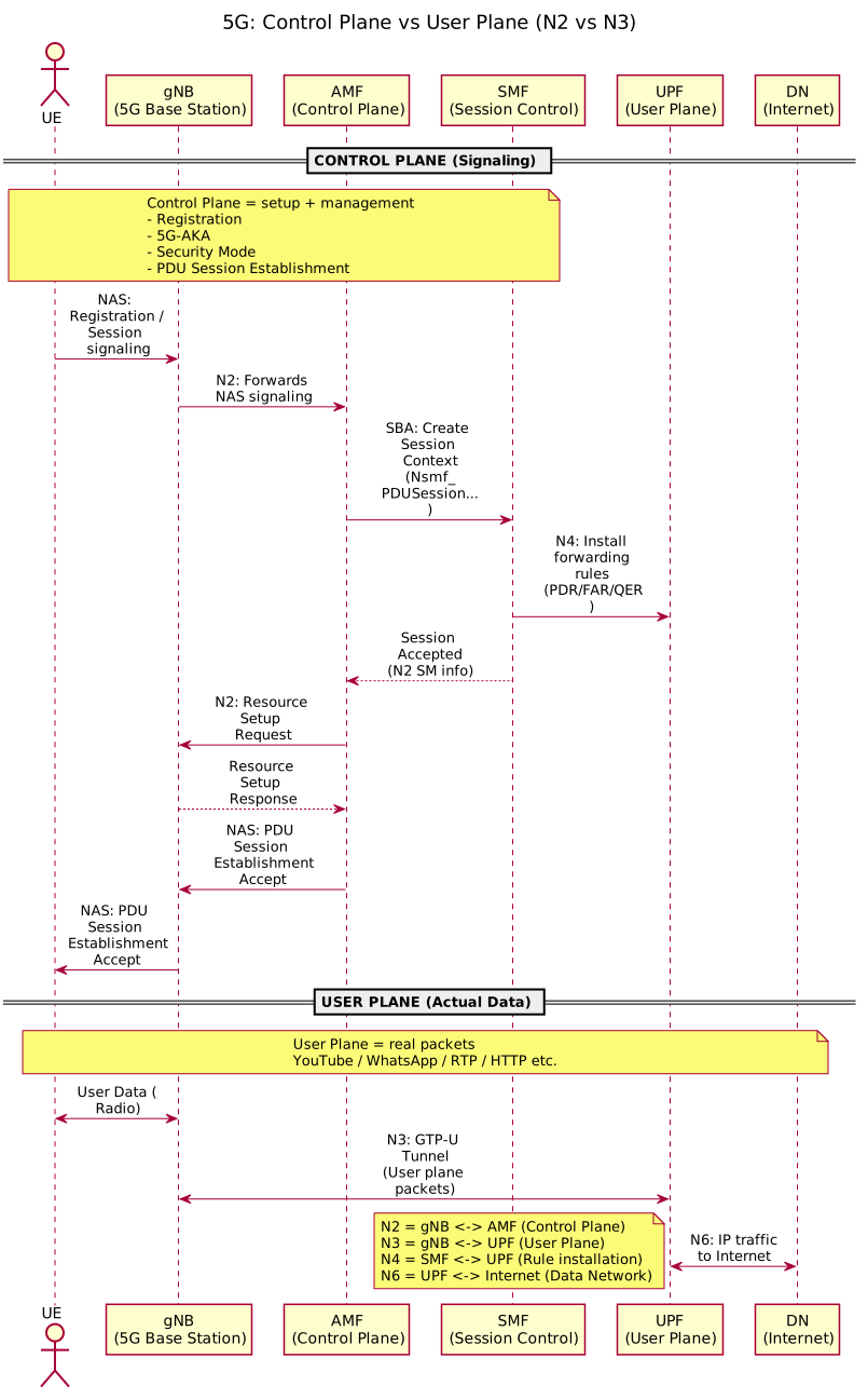
Key Separation (N2/N3 split)
5G explicitly separates CP and UP interfaces:
- N2: gNB ↔ AMF (Control Plane, NGAP signaling)
- N3: gNB ↔ UPF (User Plane, GTP-U packets)
Benefit:
- Scale CP and UP independently
- CP can be centralized, UP can be distributed (edge)
- Easier to add security controls on UP
Control Plane vs User Plane Diagram
 {:class=“diagram-img”}
Sequence diagram illustrating the separation of Control Plane (N2: gNB ↔ AMF, setup/signaling) and User Plane (N3: gNB ↔ UPF, data traffic) with N4 interface (SMF ↔ UPF) for forwarding rule configuration.
5G Interfaces (N2, N3, N4, N6) {#5g-interfaces}
N2: gNB ↔ AMF (Control Plane)
- Protocol: NGAP (NG Application Protocol)
- Purpose: NAS message relay, RAN info
- Messages: Registration, bearer allocation, RAN status
N3: gNB ↔ UPF (User Plane)
- Protocol: GTP-U (GPRS Tunneling Protocol - User Plane)
- Purpose: Tunnel user traffic from gNB to UPF
- Packets: IP packets wrapped in GTP header
N4: SMF ↔ UPF (Management Interface)
- Protocol: PFCP (Packet Forwarding Control Protocol)
- Purpose: SMF tells UPF: “Forward traffic with this QoS”
- Messages: Create/modify/delete forwarding rules, QoS parameters
N6: UPF ↔ Data Network (External Interface)
- Purpose: UPF connects to Internet, IMS, or private networks
- Protocol: Standard IP (no tunneling)
- Example: UPF has route to YouTube servers
5G-AKA Authentication {#5g-aka-authentication}
What is 5G-AKA?
5G-AKA = Authentication and Key Agreement
It’s the “login mechanism” of 5G networks:
- Mutual authentication (UE verifies network, network verifies UE)
- Derive session encryption/integrity keys
- Prevent fake base stations, replay attacks, identity theft
Why It Exists
Threats it prevents:
- Fake base station: Attacker sets up fake gNB to intercept calls
- Replay attack: Attacker re-uses old authentication response
- Stolen identity misuse: Attacker with cloned SIM tries to impersonate user
- Session hijacking: Attacker tries to steal session keys
Key Entities
-
UE/USIM
- Stores secret key K (128-256 bits)
- Derived keys are also computed on SIM
-
AMF (Access & Mobility Management)
- Orchestrates 5G-AKA
- Requests auth from AUSF
- No access to secret K
-
AUSF (Authentication Server Function)
- Validates UE’s response
- Derives session keys
- No direct access to K either
-
UDM/ARPF (Authentication & Repository Function)
- Stores secret K (in HSS equivalent)
- Generates authentication vectors
- Can only be accessed by AUSF
5G-AKA Flow (Story)
Scene: User powers on 5G phone
-
UE → AMF: Registration Request (with SUPI: subscription ID)
-
AMF → AUSF: Authentication request for this user
-
AUSF → UDM/ARPF: “Generate auth vector for this user”
-
UDM/ARPF → AUSF: Returns:
- RAND: Random challenge (128 bits)
- AUTN: Authentication token (network authenticity proof)
- XRES:* Expected response (hashed)
- K_AUSF: Key material for session
-
AUSF → AMF: Sends RAND, AUTN
-
AMF → UE: Authentication Request with RAND, AUTN
-
UE/USIM computes:
- Verifies AUTN (checks network authenticity)
- Extracts AK (Anonymity Key) = f5(K, RAND)
- Extracts SQN (sequence number)
- Verifies SQN is fresh (not replayed)
- Computes RES* = f2*(K, RAND) → (hashed and bound to serving network)
- Verifies AUTN (checks network authenticity)
-
UE → AMF: Authentication Response with RES*
-
AMF → AUSF: Sends received RES*
-
AUSF validates: Does RES* == XRES*?
- If yes: Authentication success
- Derives session keys:
- K_SEAF (network anchor key)
- K_AMF (encryption key for NAS)
- K_NASint (integrity key for NAS)
-
AMF → UE: Authentication success
- UE also derives same keys locally
- Registration completes
Where Secret K Lives
- On USIM (SIM secure chip): One copy, protected by access controls
- In UDM/ARPF database: Another copy, in secure network DB
- Never transmitted: K never leaves these locations
- Roaming: Even serving network (different country) never gets K
Why 5G uses RES*/XRES* (Not Simple RES/XRES)
4G problem: Response could be replayed or used in different network
5G fix: RES* binds response to serving network identity:
RES* = KDF(RES, RAND, SN_name)Where SN_name = Serving Network Identity
Result:
- Response generated for “Network A” won’t work for “Network B”
- Prevents roaming attacks
- Hardens interconnect scenarios
5G Voice (VoNR) {#5g-voice-vonr}
What is VoNR?
VoNR = Voice over New Radio
Similar concept to VoLTE:
- Voice is IP packets (RTP)
- Signaling is SIP (via IMS)
- Runs on 5G NR radio
VoNR vs VoLTE
| Aspect | VoLTE | VoNR |
|---|---|---|
| Radio | LTE | 5G NR |
| Latency | ~100ms | ~1ms |
| Voice Quality | HD Voice | Ultra HD Voice |
| Bandwidth | 12 kHz | 16+ kHz |
| IMS | Yes | Yes |
| Fallback | To 3G/2G | To LTE (VoLTE) |
VoNR Fallback
If VoNR unavailable (no 5G coverage):
- EPS Fallback: UE may re-attach to LTE
- Seamless transition to VoLTE
- Call setup triggers fallback automatically
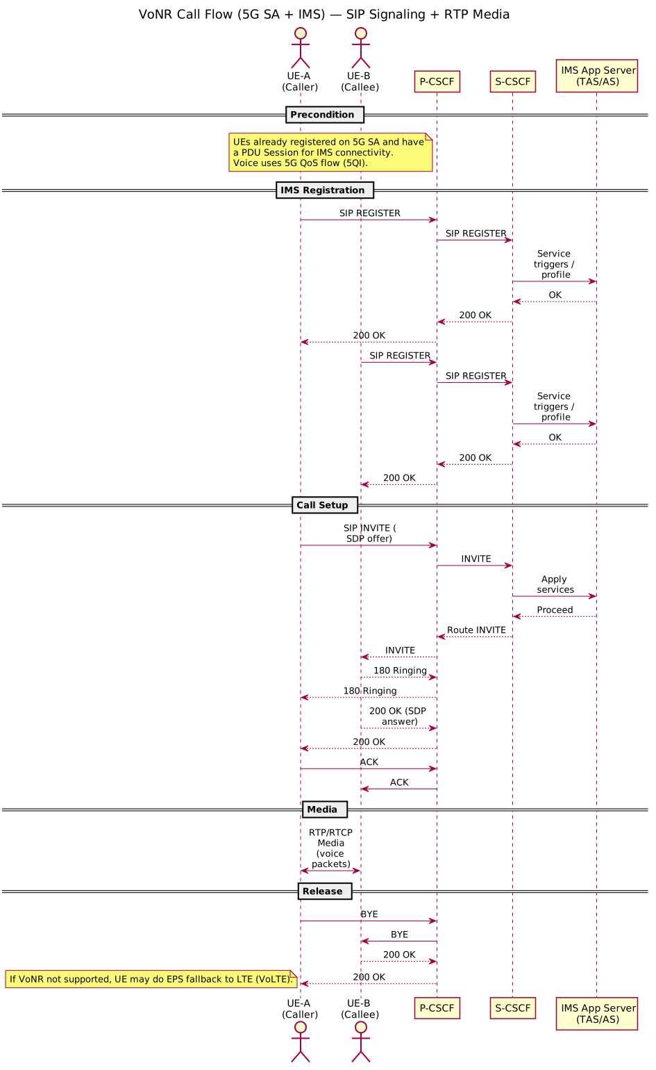
VoNR Call Flow Diagram
 {:class=“diagram-img”}
VoNR call flow showing IMS registration on 5G SA, SIP signaling via P-CSCF/S-CSCF, and RTP media with 5G QoS flow (5QI) - demonstrating ultra-low latency voice over 5G NR.
NGFW/SASE Alignment {#ngfw-sase-alignment}
Where Does Security Enforcement Fit?
In 5G, UPF is the primary data plane gateway:
- All user traffic flows through UPF (or edge UPF)
- Logical place for traffic steering, security services
5G + NGFW/SASE Integration
Typical deployment:
UE → gNB → UPF → Security/SASE → InternetOr selective routing:
UE → gNB → UPF → [ normal traffic ] → Internet
              ↓
              [ suspicious/policy traffic ] → SASE/NGFW → Internet
Security Services at UPF
- Traffic steering: Route through security chain
- Service chaining: DPI, URL filtering, threat prevention
- DPI (Deep Packet Inspection): Understand application type
- URL filtering: Block malicious, inappropriate sites
- QoS enforcement: Match control plane policies
- Data loss prevention (DLP): Prevent data exfiltration
- Threat prevention: Block malware, C2 traffic
Integration Points
- N6 interface: UPF to external networks (best point for security insertion)
- N4 interface: SMF tells UPF forwarding rules (can encode security policy)
- SASE architecture: UPF acts as local “secure gateway” for edge branch
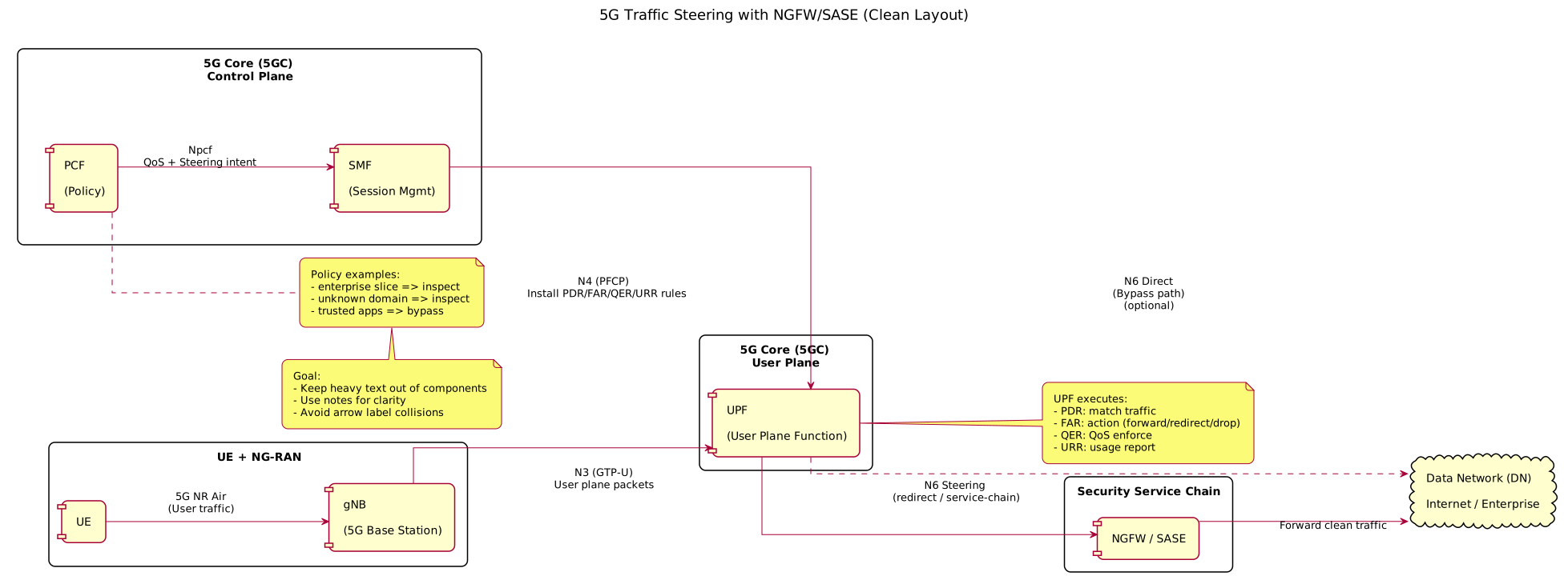
5G Security Steering: SMF→UPF Rules + Data Path
 {:class=“diagram-img”}
Sequence diagram showing 5G Security Steering: SMF→UPF Rules + Data Path (N4 + N6): PCF policy decision → SMF configures UPF via N4 → UPF forwards traffic through security chain (DPI, URL filter, threat prevention) at N6 interface before reaching Internet/DN.
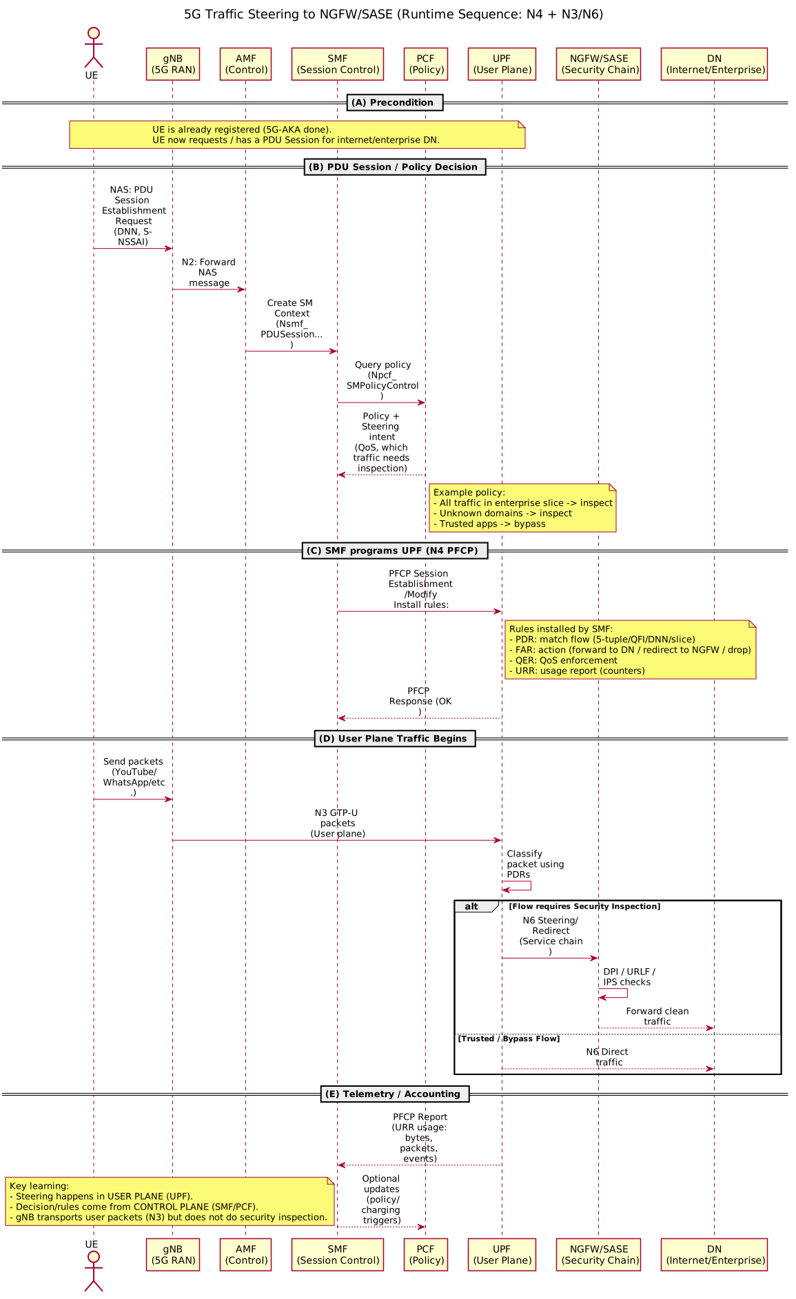
5G NGFW/SASE Integration Flow Diagram
 {:class=“diagram-img”}
Sequence diagram showing runtime traffic steering to NGFW/SASE: PCF policy decision → SMF configures UPF via N4 → UPF forwards traffic through security chain (DPI, URL filter, threat prevention) at N6 interface before reaching Internet/DN.
Key Takeaways {#key-takeaways}
-
Big Picture:
- Mobile networks provide connectivity, authentication, mobility, services
- Fundamentally different from enterprise networks
-
4G Architecture:
- EPC is element-based (MME, SGW, PGW, HSS)
- All-IP but with dedicated interfaces
- Voice via IMS (VoLTE)
-
5G Architecture:
- 5GC is service-based (AMF, SMF, UPF, UDM, AUSF, etc.)
- HTTP/2 REST APIs for NF communication
- Microservices with NRF discovery
- Simplified user plane (no SGW layer)
-
NAS vs AS:
- NAS: Core signaling (UE ↔ AMF, includes auth, registration, session setup)
- AS: Radio signaling (UE ↔ gNB, includes RRC, PDCP, RLC, MAC, PHY)
- NAS encrypted end-to-end, AS encrypted at radio layer
-
Control Plane vs User Plane:
- CP: Setup sessions (registration, bearer allocation)
- UP: Carry traffic (YouTube, voice, emails)
- 5G explicitly splits N2 (CP) and N3 (UP)
-
5G Interfaces:
- N2: Control messages gNB ↔ AMF
- N3: User traffic gNB ↔ UPF (GTP-U)
- N4: Forwarding rules SMF ↔ UPF (PFCP)
- N6: UPF ↔ Internet
-
5G-AKA:
- Mutual authentication with secret key K (on USIM + UDM)
- RES*/XRES* binding prevents replay/roaming attacks
- Session keys (K_SEAF, K_AMF) derived for NAS encryption
-
Voice:
- VoLTE: 4G voice via IMS, QCI=1 bearer
- VoNR: 5G voice via IMS, ultra-low latency
-
Security & NGFW/SASE:
- UPF is key point for data plane security insertion
- N6 interface (UPF to Internet) is best point for DPI, URL filtering
- SMF policies can steer traffic through SASE chain
- Edge UPF deployment enables local security (zero trust)
-
Key Architectural Differences (4G vs 5G):
| Aspect | 4G LTE | 5G NR |
|---|---|---|
| Core Architecture | Element-based (MME/SGW/PGW) | Service-based microservices (AMF/SMF/UPF) |
| Gateway | Separate SGW, PGW | Unified UPF |
| Latency | ~100ms | ~1ms |
| Data Rate | 300 Mbps | 10 Gbps |
| Spectrum | Sub-6 GHz | Sub-6 GHz + mmWave |
| NF Communication | Dedicated interfaces | REST APIs, service discovery |
| MIMO | Limited (4-8 antennas) | Massive MIMO (64+ antennas) |
| Network Slicing | No | Yes (create virtual networks) |
| Authentication | KASME key derivation | 5G-AKA with RES* binding |
| Voice | VoLTE | VoNR |