🧭 Architecture Overview — The Three Planes in Practice
Module 01 gave us the mental model: every firewall splits into a data plane, a control plane, and a management plane. This module maps that model onto a real, working NGFW platform — naming the actual engines, showing how they connect, and explaining why the pieces are split up the way they are.
The single most important idea to hold onto:
The data plane is a user-space packet engine (VPP), and it is the hub. Everything else — the intrusion-prevention engine, the VPN key negotiator, the management bridge — is a separate process that plugs into VPP through a well-defined channel.
Table of Contents
- The Big Picture
- Component Inventory
- Data Plane: VPP as the Hub
- Control Plane: Setting Up Sessions
- Management Plane: Operating the Box
- How the Planes Talk to Each Other
- Orchestration & Startup
- The Deployment Shape
- Why This Design?
- Key Takeaways
- What’s Next
The Big Picture {#big-picture}
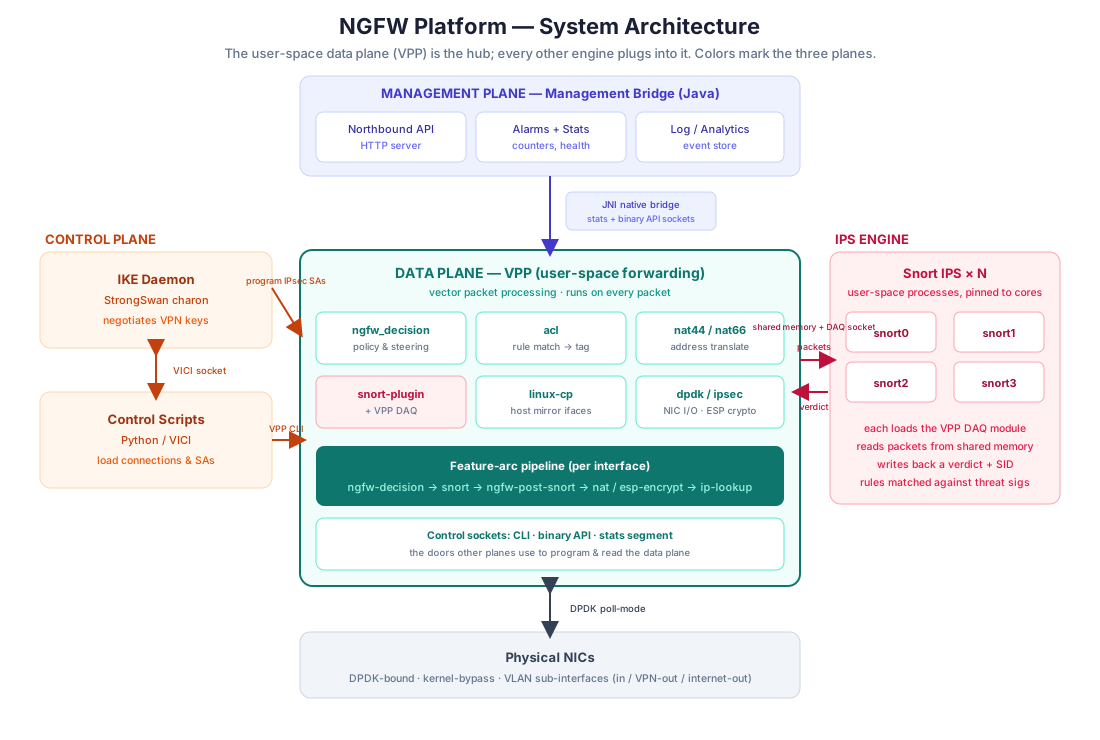
Here is the whole system on one page. Spend a minute on it — every later module zooms into one region of this diagram.
 {:class=“diagram-img”}
VPP (teal, center) is the fast path. The IPS engine (Snort, right) inspects packets over shared memory. The control plane (orange, left) negotiates VPN tunnels and programs the data plane. The management bridge (indigo, top) reads counters and serves them northbound. Physical NICs (bottom) are bound to DPDK for kernel-bypass I/O.
The thing that surprises most newcomers: this is not one monolithic program. It’s a set of cooperating processes written in different languages, deliberately kept separate so each can be developed, scaled, crashed, and restarted on its own. The art is in the interfaces between them — and most of this module is about those interfaces.
Component Inventory {#component-inventory}
| Component | Plane | Language | Role |
|---|---|---|---|
| VPP (Vector Packet Processing) | Data | C | The user-space forwarding engine — the fast path. Hosts all custom plugins. |
ngfw_decision plugin | Data | C | The firewall “brain”: turns a policy match into an action and steers each packet. |
acl plugin | Data | C | Classifies packets against rules and tags each with a steering action. |
nat44 / nat66 plugins | Data | C | IPv4 and IPv6 network address translation. |
snort plugin + VPP DAQ | Data | C | The bridge that hands packets to Snort and reads verdicts back. |
linux-cp plugin | Data | C | Mirrors VPP interfaces into the Linux host so control-plane apps can use them. |
dpdk / ipsec plugins | Data | C | NIC I/O (kernel bypass) and ESP encryption/decryption. |
| Snort 3 | Data (inspection) | C++ | The intrusion-prevention engine; runs as N separate processes. |
| StrongSwan (charon) | Control | C | The IKE daemon that negotiates VPN keys and parameters. |
| Control scripts | Control | Python | Glue that drives StrongSwan (load connections, initiate/rekey tunnels) over VICI. |
| Management bridge | Management | Java + JNI (C) | Reads VPP counters/stats and exposes them to a northbound management system; raises alarms. |
| Orchestrator | — | Bash | A startup script that templates the config and launches everything in order. |
Four languages, three planes, one packet path. Let’s take the planes one at a time.
Data Plane: VPP as the Hub {#data-plane}
Everything that touches a packet lives inside VPP. If you did the VPP modules, this is where that knowledge pays off; if not, here’s the 30-second version.
VPP processes packets as vectors through a graph of nodes. Instead of pushing one packet all the way through the stack and then fetching the next, VPP grabs a batch (vector) of packets and runs the whole batch through one graph node, then the next, then the next. Batching keeps code and data hot in CPU cache, which is what makes line-rate processing possible.
Feature arcs are how you insert custom logic into that graph. An “arc” is an ordered chain of optional features that a packet traverses for a given traffic class (e.g. ip4-unicast). This platform registers its own nodes onto that arc. The order — confirmed in the plugin source — is:
ngfw-decision-ip4 → snort-ip4-input → ngfw-post-snort-feature → ip4-lookup(and a mirror-image -ip6 chain for IPv6). In plain English:
ngfw-decisionruns first. It looks at the ACL plugin’s per-rule steering tag for the packet and decides an action: pass, drop, or “inspect with Snort, then do NAT / encrypt / forward”. If the action needs Snort, it stashes a small note for later and lets the packet continue down the arc.snort-ip4-inputhands the packet to the Snort engine for deep inspection (more on the mechanism in [Module 05]). Snort’s verdict either drops the packet or lets it continue.ngfw-post-snort-featureruns after Snort. It reads the note left in step 1 and finishes the job: forward the survivor to a route lookup, or divert it into IPsec encryption.ip4-lookupis the normal VPP route lookup that sends the packet out.
The two custom decision nodes coordinate by leaving a small per-packet note in a scratch area that travels with the packet buffer (VPP gives each packet buffer some opaque metadata slots). The decision node writes the note before Snort; the post-Snort node reads it after. A one-byte cookie marks the note as “ours,” so the post-Snort node can tell apart packets this pipeline tagged from packets that arrived by some other path. This little handshake — decide early, carry the decision forward, act on it later — is the beating heart of the data plane, and Module 04 traces it packet-by-packet.
The ACL plugin feeds the decision node. It matches each packet against the rule set and emits a steering tag — values like “NAT then forward,” “NAT then Snort,” “NAT then Snort then encrypt,” or “drop.” The decision node translates that tag into its own action enum. Keeping classification (ACL) separate from policy dispatch (decision) is a clean split: the ACL answers “which rule matched and what does it want?”, and the decision node answers “so what do I actually do with this packet?”
Control Plane: Setting Up Sessions {#control-plane}
The control plane handles the one thing the data plane can’t do on the hot path: the slow, occasional negotiation that sets up encrypted tunnels.
- StrongSwan
charonis the IKE (Internet Key Exchange) daemon. When a VPN tunnel needs to come up, charon does the cryptographic handshake with the remote peer and produces the Security Associations (SAs) — the agreed keys and parameters for the tunnel. - Instead of programming those SAs into the Linux kernel (the default), a VPP integration pushes them straight into VPP’s IPsec engine, so the data plane does the actual ESP encryption at line rate. The control plane negotiates; the data plane encrypts.
- Python control scripts drive charon over its VICI management interface (a local socket StrongSwan exposes for automation): load tunnel definitions, initiate or tear down connections, trigger rekeys. The data plane can even reach back to these scripts — a VPP CLI command can shell out to a script to, say, list active tunnels — so an operator gets one consistent view.
The takeaway: key negotiation is a control-plane job that runs rarely; packet encryption is a data-plane job that runs constantly. Splitting them is what lets a software box do IPsec at high throughput.
Management Plane: Operating the Box {#management-plane}
The management plane is how a human or an upstream Network Management System (NMS) sees and runs the firewall — without ever sitting in the packet path.
A management bridge (a Java application) is the northbound face of the box. Its job is to read the firewall’s counters and health, and publish them upward. The interesting part is how a Java program reads counters out of a C packet engine:
- A small JNI native library (C) is the shim between Java and VPP. JNI (“Java Native Interface”) lets Java call into native C code.
- Through that shim, the bridge uses two of VPP’s client interfaces:
- the stats segment — a shared-memory region VPP publishes counters into (packets, bytes, per-node stats). Reading it is cheap and doesn’t disturb the data plane.
- the binary API — a message socket for issuing commands, e.g. “clear these counters.”
- The Java layer then serves that data northbound over HTTP, raises alarms, and ships events to a log/analytics store.
So the flow is: VPP counters → JNI shim → Java bridge → HTTP / alarms / logs → operator or NMS. Because it only reads shared memory and occasionally sends an API message, the management plane can restart or fail without dropping a single packet.
How the Planes Talk to Each Other {#how-planes-talk}
The whole system is really defined by its inter-process channels. Here they are in one table — this is the “API surface” between the moving parts:
| From → To | Channel | What flows |
|---|---|---|
| VPP nodes → VPP nodes | Per-packet buffer metadata (opaque slots + cookie) | The steering decision, carried with the packet across the pipeline |
| VPP ↔ Snort | Shared memory + a DAQ socket | Packets out to Snort; verdict + rule ID back |
| Control scripts ↔ StrongSwan | VICI socket | Load/initiate/terminate/rekey tunnels |
| StrongSwan → VPP | IPsec SA programming (VPP integration) | Negotiated keys installed into the data-plane crypto |
| VPP CLI → control scripts | Process invocation | Operator commands that need control-plane data |
| Management bridge → VPP | JNI → stats segment + binary API sockets | Read counters; clear counters |
| Management bridge → NMS | HTTP / alarms / log feed | Northbound telemetry |
| NIC ↔ VPP | DPDK poll-mode | Raw packets in and out, kernel-bypassed |
If you understand this table, you understand the architecture. Every module from here on is a deep-dive into one row.
Orchestration & Startup {#orchestration}
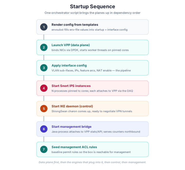
None of these processes start themselves. A single orchestrator script (Bash) brings the system up in dependency order — and the order matters, because each engine needs the one before it to already be running.
 {:class=“diagram-img”}
The data plane comes up first, then the engines that attach to it, then control, then management.
- Render config from templates. The platform keeps its configuration as templates with
${PLACEHOLDER}variables, filled in from an environment file at startup (viaenvsubst). This is how one image adapts to different deployments — core counts, interface names, addresses, and instance counts are all parameters, not hard-coded values. - Launch VPP. It binds the NICs through DPDK and spins up worker threads pinned to specific CPU cores.
- Apply the interface config. A generated VPP CLI script creates the VLAN sub-interfaces, assigns addresses, enables the feature arcs (the pipeline!), and turns on NAT.
- Start the Snort instances. N inspection processes, each pinned to a core and attached to VPP through the DAQ.
- Start the IKE daemon so VPN tunnels can be negotiated.
- Start the management bridge so counters flow northbound.
- Seed baseline ACL rules so the box is reachable for management traffic.
Why templating matters for a newcomer: when you want to run this on your own hardware, you don’t edit source — you edit the environment file. Interface names, CPU pinning, how many Snort instances to run, and the addressing all live there.
The Deployment Shape {#deployment-shape}
A few structural facts that make the rest concrete:
- It runs as a container/appliance. The orchestrator script is the entry point; when it finishes bringing services up, it tails a log to keep the process alive.
- Traffic is separated with VLAN sub-interfaces. Physical ports are sliced into logical interfaces — typically an inbound interface (traffic to be inspected), a VPN-out interface (traffic leaving over IPsec tunnels), and an internet-out interface (traffic going straight out). Steering a flow to the right egress is part of what the decision node decides.
- CPU cores are a managed resource. VPP’s main thread, VPP’s worker threads, and each Snort instance are pinned to distinct cores. On a packet engine, letting the OS scheduler move a busy thread between cores would wreck cache locality and jitter — so nothing is left to chance.
Why This Design? {#why-this-design}
It’s worth stepping back and asking why build it as separate cooperating processes rather than one program. The reasons are the recurring themes of data-plane engineering:
- Separation of concerns. Packet forwarding, intrusion detection, and key negotiation are genuinely different problems with different performance profiles. Keeping them apart lets each use the best tool — VPP for forwarding, a mature IPS for detection, a mature IKE daemon for crypto negotiation.
- Failure isolation. The management bridge can crash without dropping traffic. A Snort instance can be restarted while VPP keeps forwarding. The blast radius of any one failure is small.
- Independent scaling. Need more inspection throughput? Run more Snort instances on more cores. The data plane doesn’t change.
- Reuse over reinvention. Snort and StrongSwan are battle-tested open-source projects. Rather than re-implement an IPS or an IKE stack inside VPP, the platform integrates them through clean channels (the DAQ, VICI, SA programming).
That last point is the theme of the whole codebase: VPP provides the fast path and the plumbing; proven engines provide the smarts; thin, well-defined bridges connect them.
Key Takeaways {#key-takeaways}
- The platform is several cooperating processes, not a monolith — connected by well-defined channels.
- VPP is the data-plane hub. Custom C plugins (
ngfw_decision,acl,nat,snort) run the firewall logic inside VPP’s node graph. - The pipeline is a feature arc:
ngfw-decision → snort → ngfw-post-snort → nat/ipsec → lookup, coordinated by a small per-packet note (with a cookie) carried in the packet buffer. - The control plane (StrongSwan + Python/VICI) negotiates VPN keys and programs the data plane; the data plane does the actual encryption.
- The management plane (Java + JNI) reads VPP’s stats segment and binary API and serves telemetry northbound — reading only, never in the packet path.
- A Bash orchestrator brings the planes up in dependency order, using templated config driven by an environment file.
- The design choices — separation of concerns, failure isolation, independent scaling, reuse of proven engines — are the standard trade-offs of high-performance networking.
What’s Next {#whats-next}
We’ve named the pieces and their channels. The next module goes inside the data plane: how VPP’s graph and feature arcs actually work, and how a custom plugin registers a node onto the pipeline — the foundation for reading the ngfw_decision and acl source.