⚙️ The VPP Data Plane — Graph, Nodes & Feature Arcs
Module 02 said “VPP is the hub” and left it there. This module opens the hub. By the end you’ll understand VPP’s packet graph, how a node is written, how feature arcs let you slot custom logic into the pipeline, and how packets carry a decision from one node to the next. This is the foundation for reading the actual firewall plugin code — so we’ll keep tying each concept back to the ngfw-decision and ngfw-post-snort nodes you met earlier.
New to VPP entirely? Skim the VPP fundamentals first, but this module is written to stand on its own.
Table of Contents
- The Graph Model
- Why “Vector” Processing
- Anatomy of a Node
- Registering a Node
- Feature Arcs: Pluggable Pipelines
- Passing Data Between Nodes
- Putting It Together: the Firewall Arc
- Observing the Pipeline
- Recipe: Add Your Own Node
- Key Takeaways
- What’s Next
The Graph Model {#graph-model}
VPP models packet processing as a directed graph of nodes. Each node is a small function that does one job — validate an IPv4 header, look up a route, encrypt with ESP — and then points each packet at the next node. A packet’s path through the firewall is a walk through this graph.
There are three node flavors you’ll meet:
| Node type | Role | Example |
|---|---|---|
| Input | Pulls packets off the NIC (or another source) and injects them into the graph. | dpdk-input |
| Internal | The workhorses — take a batch of packets, do work, forward to the next node. | ip4-input, ngfw-decision-ip4 |
| Process | Cooperative “background” nodes for timers and control tasks (not on the packet hot path). | housekeeping |
The custom firewall nodes (ngfw-decision-ip4, ngfw-post-snort-feature) are internal nodes. They receive a batch of packets, decide what to do, and hand each packet to whichever node comes next.
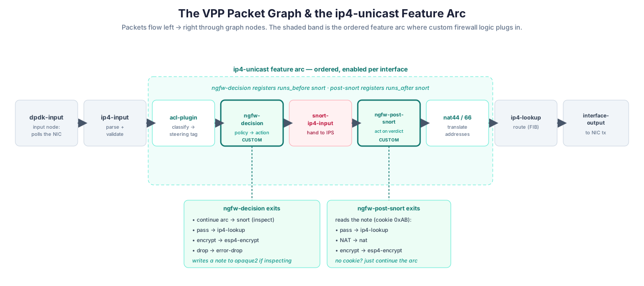 {:class=“diagram-img”}
Packets flow left → right. The shaded band is the ip4-unicast feature arc — an ordered list of optional features. The two teal nodes are this platform’s custom additions; the callouts show where each can send a packet.
Why “Vector” Processing {#vector-processing}
The “VPP” in VPP is Vector Packet Processing, and this is the idea that makes software forwarding fast enough to matter.
A naive stack takes one packet and runs it through every layer (parse → route → encrypt → transmit) before fetching the next. That thrashes the CPU’s instruction cache: by the time packet 2 arrives, the code for “parse” has been evicted to make room for “encrypt.”
VPP inverts the loop. It grabs a vector — a batch of up to 256 packets, called a frame — and runs the entire batch through one node before moving the batch to the next node. So the “parse” code runs 256 times in a row while it’s hot in cache, then the “route” code runs 256 times, and so on.
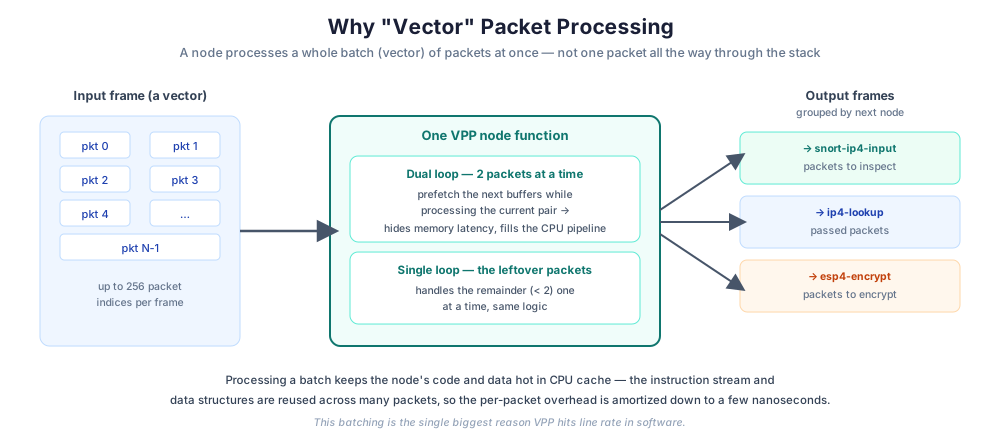 {:class=“diagram-img”}
A node processes a whole frame at once, often two packets per loop iteration (a “dual loop”) so it can prefetch the next buffers while working on the current pair. Output packets are regrouped by their next node.
Two performance tricks ride along with this:
- Dual (or quad) loops. The node processes 2 (or 4) packets per iteration and issues a prefetch for the next buffers before touching the current ones. While the CPU waits on memory for packets 2 and 3, it’s busy computing on packets 0 and 1 — memory latency is hidden behind useful work. You saw this in the real node: a
while (n_left_from >= 4 …)dual loop followed by awhile (n_left_from > 0 …)single loop for the remainder. - Cache-hot code and data. Because one node’s code runs across the whole batch, the instructions and lookup tables stay in L1/L2 cache.
This is the payoff of everything in the DPDK track — huge pages, NUMA-local buffers, poll-mode drivers — all feeding batches into a graph of cache-friendly nodes.
Anatomy of a Node {#node-anatomy}
Every internal node is a function with the same shape. Here’s the skeleton (simplified from the real firewall node, with the boilerplate that never changes):
VLIB_NODE_FN (my_node) (vlib_main_t *vm,
                        vlib_node_runtime_t *node,
                        vlib_frame_t *frame)
{
  u32 n_left_from, *from, *to_next;
  u32 next_index = node->cached_next_index;

  from        = vlib_frame_vector_args (frame); /* the input vector      */
  n_left_from = frame->n_vectors;               /* how many packets      */

  while (n_left_from > 0)
    {
      u32 n_left_to_next;
      vlib_get_next_frame (vm, node, next_index, to_next, n_left_to_next);

      /* ---- dual loop: two packets per iteration ---- */
      while (n_left_from >= 4 && n_left_to_next >= 2)
        {
          /* prefetch the buffers two ahead */
          vlib_prefetch_buffer_with_index (vm, from[2], LOAD);
          vlib_prefetch_buffer_with_index (vm, from[3], LOAD);

          u32 bi0 = from[0], bi1 = from[1];
          vlib_buffer_t *b0 = vlib_get_buffer (vm, bi0);
          vlib_buffer_t *b1 = vlib_get_buffer (vm, bi1);

          u16 next0 = decide (b0);   /* <-- your logic: pick the next node */
          u16 next1 = decide (b1);

          /* enqueue both packets toward their chosen next nodes */
          vlib_validate_buffer_enqueue_x2 (vm, node, next_index,
                                           to_next, n_left_to_next,
                                           bi0, bi1, next0, next1);
        }

      /* ---- single loop: the leftover packets, one at a time ---- */
      while (n_left_from > 0 && n_left_to_next > 0)
        {
          u32 bi0 = from[0];
          vlib_buffer_t *b0 = vlib_get_buffer (vm, bi0);
          u16 next0 = decide (b0);
          vlib_validate_buffer_enqueue_x1 (vm, node, next_index,
                                           to_next, n_left_to_next,
                                           bi0, next0);
        }

      vlib_put_next_frame (vm, node, next_index, n_left_to_next);
    }
  return frame->n_vectors;
}
The whole node is “for each packet in the batch, decide a next node, and enqueue it there.” Everything else — decide() — is your firewall logic. In ngfw-decision, decide() reads the ACL tag and returns one of PASS → ip4-lookup, DROP → error-drop, ENCRYPT → esp4-encrypt, or continue-the-arc → snort.
Registering a Node {#registering-a-node}
A node function isn’t usable until you register it and declare its possible next nodes. Registration is a static declaration:
VLIB_REGISTER_NODE (my_node) = {
  .name         = "ngfw-decision-ip4",   /* the name you see in `show trace` */
  .vector_size  = sizeof (u32),          /* each vector slot is a buffer index */
  .type         = VLIB_NODE_TYPE_INTERNAL,
  .format_trace = format_my_trace,       /* how to pretty-print a trace record */
  .n_errors     = MY_N_ERROR,            /* per-node counters */
  .error_strings = my_error_strings,

  /* The fixed set of nodes this node can send packets to.
     Your code returns one of these slot numbers as "next". */
  .n_next_nodes = MY_N_NEXT,
  .next_nodes   = {
    [MY_NEXT_ARC]  = "ip4-drop",     /* placeholder; filled in at runtime */
    [MY_NEXT_PASS] = "ip4-lookup",
    [MY_NEXT_ENC]  = "esp4-encrypt",
    [MY_NEXT_DROP] = "error-drop",
  },
};
Key idea: a node’s next nodes are a fixed, numbered list. Your hot-loop returns a small integer (the slot), not a node name — resolving names to indices at registration time keeps the hot path branch-cheap. This is exactly the next_nodes[] table you saw in the real plugin, where slot PASS maps to ip4-lookup, ENC to esp4-encrypt, and DROP to error-drop.
Feature Arcs: Pluggable Pipelines {#feature-arcs}
Here’s the piece that makes VPP extensible without editing VPP itself.
A feature arc is an ordered chain of optional features that a packet traverses for a traffic class. ip4-unicast is the arc every routed IPv4 packet goes through. Plugins register onto an arc and declare their ordering constraints — and each feature can be turned on or off per interface.
You register a node onto an arc like this:
VNET_FEATURE_INIT (ngfw_decision_ip4_feature, static) = {
  .arc_name    = "ip4-unicast",
  .node_name   = "ngfw-decision-ip4",
  .runs_after  = VNET_FEATURES ("acl-plugin-in-ip4-fa"), /* need the ACL tag first */
  .runs_before = VNET_FEATURES ("snort-ip4-input"),      /* decide before inspecting */
};
Three things to notice, all straight from the real code:
-
runs_after/runs_beforeexpress ordering, not position. You don’t say “I’m feature #3.” You say “put me after the ACL plugin and before Snort,” and VPP computes a consistent order (a topological sort). That’s whyngfw-decisionreliably sees the ACL’s steering tag: it declaredruns_afterthe ACL feature. -
The post-Snort node is a separate feature that declares
runs_after ("snort-ip4-input"), so it lands after inspection — closing the “decide before, act after” bracket around Snort. -
Features are enabled per interface. Registering makes a feature available; a packet only traverses it if the feature is enabled on that interface:
vpp# set interface feature <iface> ngfw-decision-ip4 arc ip4-unicast
vpp# set interface feature <iface> ngfw-post-snort-feature arc ip4-unicast
That’s what the platform’s interface config script does at startup for the protected interfaces (and the mirror
-ip6features on theip6-unicastarc).
So the firewall pipeline isn’t hard-wired — it’s assembled at runtime from independently-registered features, ordered by their constraints, and switched on per interface. Want to insert a new inspection step between the decision and Snort? Register a feature with the right runs_after/runs_before and enable it. No core changes.
Passing Data Between Nodes {#buffer-metadata}
Nodes are separate functions running at different times (remember: the whole batch passes through node A, then the whole batch passes through node B). So how does ngfw-decision tell the later ngfw-post-snort node “this packet should be NAT’d, not encrypted”?
The answer: each packet buffer carries scratch metadata that travels with it through the graph. VPP’s vlib_buffer_t has two opaque metadata areas:
opaque[]— used by many built-in features (and, here, by the Snort plugin for its own bookkeeping).opaque2[]— a second, independent area this platform uses for the firewall’s per-packet note.
The decision node writes a small struct into opaque2 before the packet reaches Snort:
/* conceptual layout of the per-packet note in opaque2 */
typedef struct {
  acl_user_action_t acl_action;  /* offset 0: written by the ACL plugin  */
  u8   cookie;                   /* 0xAB marks "this note is ours"       */
  u8   post_action;              /* PASS / NAT / IPSEC after Snort        */
  u32  out_sa_index;             /* which IPsec SA, if encrypting         */
  u32  out_sw_if_index;          /* which interface, if forwarding        */
} pkt_meta_t;
Then ngfw-post-snort (running after Snort) reads it back:
pkt_meta_t *m = (pkt_meta_t *) b->opaque2;
if (m->cookie == 0xAB) {          /* is this note ours? */
    switch (m->post_action) {
      case PASS:  next = NEXT_LOOKUP;  break;
      case NAT:   next = NEXT_NAT;     break;
      case IPSEC: vnet_buffer(b)->ipsec.sad_index = m->out_sa_index;
                  next = NEXT_ENCRYPT; break;
    }
    m->cookie = 0;                /* consume it, so it can't be reprocessed */
}
Two design details worth calling out, because they’re the kind of thing that bites you:
- The one-byte cookie (
0xAB) is a validity marker. A packet can reach Snort by paths other than the firewall decision node; without the cookie, the post-Snort node would misread stale bytes as a command. Checking the cookie means “only act on packets I tagged.” - Field ordering is deliberate. The ACL plugin writes its tag to the first 4 bytes of
opaque2. The firewall’s note putsacl_actionfirst so the two don’t collide — a compile-time assertion enforces that the field stays at offset 0. This is the sort of constraint that lives in a comment and aSTATIC_ASSERT, and it’s exactly why reading the real header pays off.
This “write a note before, read it after” pattern is how any two VPP nodes coordinate across the graph. It’s the data-plane equivalent of passing context down a call chain — except the “call chain” is spread across separate node invocations.
Putting It Together: the Firewall Arc {#firewall-arc}
Now the whole pipeline reads cleanly. For an IPv4 packet on a protected interface:
ip4-inputvalidates the header and pushes the packet onto theip4-unicastarc.acl-pluginmatches the packet and writes a steering tag intoopaque2[0..3].ngfw-decision-ip4(registeredruns_afterACL,runs_beforeSnort) reads that tag, picks an action, and either short-circuits (pass/drop/encrypt) or writes theopaque2note + cookie and lets the arc continue.snort-ip4-inputhands the packet to the IPS. A drop verdict never comes back; a pass continues the arc.ngfw-post-snort-feature(registeredruns_afterSnort) reads the note and finishes: forward, NAT, or encrypt.ip4-lookup(oresp4-encrypt, ornat) takes it from there.
Every arrow in that list is either a runs_before/after constraint or an opaque2 note. That’s the entire mechanism.
Observing the Pipeline {#observing}
A huge practical advantage of VPP — and a lifesaver when you start contributing — is that the graph is introspectable at runtime from the VPP CLI:
| Command | What it shows |
|---|---|
show runtime | Per-node call counts, vectors processed, and clocks-per-packet — find hot nodes. |
show node counters | The per-node error/event counters (e.g. “passed”, “dropped”, “sent to Snort”). |
trace add dpdk-input 50 then show trace | A step-by-step record of 50 packets walking the graph, node by node. |
show interface features <iface> | Which features are enabled on an interface, in order — see your arc. |
The real firewall node wires into all of these: it defines error counters ("Passed plain", "Sent to Snort", "Dropped by policy", …) that increment as packets take each path, and a trace format that prints the matched rule, action, ACL tag, and chosen next node for every traced packet. When you’re debugging “why did this packet get dropped?”, you trace add, send the packet, and show trace reads out exactly which node made which decision. There’s also an event-log (elog) path for high-frequency, low-overhead tracing.
This is the newcomer’s superpower: you don’t have to read the code and guess the packet’s path — you can make VPP tell you.
Recipe: Add Your Own Node {#recipe}
Pulling it together, here’s the minimal checklist to insert a new step into the firewall pipeline — the shape of most contributions you’ll make:
- Write the node function (
VLIB_NODE_FN) with the dual/single loop skeleton. Put your logic in the per-packetdecide(). - Define your next-node enum and register the node (
VLIB_REGISTER_NODE) with thenext_nodes[]table, error strings, and a trace formatter. - Register it on an arc (
VNET_FEATURE_INIT) with the rightruns_after/runs_beforeso it lands where you need it relative to ACL, Snort, and NAT. - Coordinate via
opaque2if a later node needs your decision — write a struct + cookie, read and consume it downstream. - Enable it per interface in the startup config script.
- Add counters + a trace format so you can see it working with
show node countersandshow trace. - Build the plugin and reload VPP.
Step 7 — the build, and where the plugin sources live — is the subject of the Contributor’s Guide later in this track.
Key Takeaways {#key-takeaways}
- VPP is a graph of nodes; a packet’s journey is a walk through that graph, and each node just picks the next node.
- Vector processing runs a whole batch through one node at a time — cache-hot code + prefetching dual loops are why software forwarding hits line rate.
- A node is a fixed-shape function (dual loop + single loop) plus a registration that declares its numbered
next_nodes[]. - Feature arcs let plugins insert nodes into the pipeline by declaring ordering constraints (
runs_before/runs_after), and features are enabled per interface — the pipeline is assembled at runtime, not hard-coded. - Nodes coordinate by leaving a note in the packet buffer (
opaque2), guarded by a cookie so only the intended node acts on it. - The firewall arc is just: ACL tags → decision decides (before Snort) → Snort inspects → post-Snort acts (after Snort) — every link is a
runs_*constraint or anopaque2note. - The graph is observable live (
show runtime,show node counters,trace add+show trace) — use it to watch packets instead of guessing.
What’s Next {#whats-next}
You now know how the pipeline is built and how packets carry decisions through it. The next module spends a full packet’s-eye view walking a single connection through the whole firewall — ACL match, decision, Snort, NAT, IPsec — tying the mechanism to a concrete end-to-end story.